Home
 |
LogixPro |
|
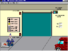
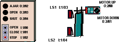
The ProSim-II Door Simulation From the Simulations Menu at the top of the screen, Select the Door Simulation. Take the time to familiarize yourself with the components used in the Door system, and take particular note of the current state of the limit switches. When the door is in the closed position, both limit switches are in their activated state (Not Normal). Run your mouse over each switch, and you should see a tool-tip text box appear, which denotes that the selected switch is wired using a set of Normally Open contacts. With the door fully closed, what signal level would you expect to see at the limit switch inputs I:1/03 and I:1/04? To confirm your assessment of the current limit switch states, place the PLC into the RUN mode which will initiate scanning. Now open the Data Table display by clicking on the Data Table icon located on the toolbar (3rd from right) at the top of the screen. When you have the Data Table showing, select the "Input Table" from the drop down Table list box. You should now be able to see the current state of each bit associated with input card I:1. You should also note that bit I:1/02 is also in a High or True state. Use your mouse to press the Stop switch on the Control Panel a few times, and note the results. Don't continue on with the exercise until you are confident that you understand the rational of the observed results. 
Student Programming Exercise #1: In this exercise we want you to apply your knowledge of Relay Logic Instructions to design a program which will control the ProSim-II Door. The Door System includes a Reversible Motor, a pair of Limit Switches and a Control Panel, all connected to your PLC. The program you create will monitor and control this equipment while adhering to the following criteria:
It is your responsibility to fully design, document, debug, and test your Program. Avoid the use of OTL or OTU latching instructions, and make a concerted effort to minimize the number of rungs employed. Ensure that you have made effective use of both instruction and rung comments to clearly document your program. All I/O components referenced within your program should be clearly labeled, and rung comments should be employed to add additional clarity as required. Student Programming Exercise #2: In this exercise we want you to apply your knowledge of Relay Logic Instructions to design a program which will maintain the appropriate door movement once initiated by the operator. The Opening or Closing operation of the door will continue to completion even if the operator releases the pushbutton which initiated the movement. The program will adhere to the following criteria:
It is your responsibility to fully design, document, debug, and test your Program. Avoid the use of OTL or OTU latching instructions, and make a concerted effort to minimize the number of rungs employed. As before, ensure that you have made effective use of both instruction and rung comments to clearly document your program. Student Programming Exercise #3: In this exercise we want to introduce you to a simple programming technique for adding a bit of "Flash" to your program. We want you to make use of the PLC's Free Running Timer which can be viewed in the Data Table Display at location S2:4. This integer word contains a count which is incremented continuously by the PLC when it is in the Run mode, and it can come in quite handy at times for variety of purposes. In this exercise we want you to utilize this word as follows: With the PLC in the Run mode, Display word S2:4 utilizing the Data Table display. Ensure that the Radix is set to Binary so that you can view the individual bits within the word. You should see a binary count in progress where the rate of change of each bit is directly related to it's position within the word. Bit 0 will have the highest rate, while Bit 1 will be 1/2 as fast as Bit 0, and Bit 2 half as fast as 1 etc. etc. We want you to add a Lamp Flasher to your program by monitoring the state of one of these bits with an XIC instruction. I'm going to suggest using Bit 4 for this purpose, but depending upon the speed of your computer you may elect to substitute another Bit. With an actual AB PLC, the rate is consistent, but with LogixPro it varies from computer to computer. Place an XIC instruction addressed to S:4/4 on the rung which controls either the Open or Shut Lamp in your previous program. Now download and Run this modified program to see the flashing effect achieved. The Lamp should flash at a reasonable rate whenever your program energizes the selected Lamp. Now modify your program so that the following criteria is met:
As before, ensure that you have made effective use of both instruction and rung comments to clearly document your program. Supplemental Programming Exercise #4: We do not recommend proceeding with this exercise if you do not have an instructor or experienced PLC programmer to call upon for assistance. In this exercise we want you to modify your program so that it adheres to this additional criteria:
...... |